
Technical Guide to Core Materials and Sizing: CRGO, Permalloy, and Thin Strip Parameters
Short answer: a transformer core is fixed by four measurable decisions — material family, strip thickness, core loss ceiling, and dimensional envelope. CRGO silicon steel covers most power-frequency duty; grain-oriented laminated steel held a 79.6% share of the transformer core market by material type in 2024 (Mordor Intelligence). Permalloy grades 1J85, 1J79 and 1J50 take over where permeability and measurement precision matter more than bulk power handling. Thin strip cores in 0.05–0.15 mm gauges cover pulse and higher-frequency duty. Sizing then follows: NCW no-cut toroidal cores run from 50–200 mm core diameter at 100–5000 VA with core loss ≤1.0 W/kg at 1.5T, 50Hz, while custom toroidal cores extend to OD 30–300 mm, ID 15–200 mm, H 10–150 mm and 50 VA–10 kVA with ≤1.2 W/kg.

Why Core Specifications Fail Before Manufacturing Starts
Most transformer core problems are not manufacturing defects. They are incomplete specifications. A drawing that names a shape — toroidal, EI, CD — but leaves material, gauge, loss ceiling or dimensional envelope open forces the supplier to fill the gap, and the assumption usually lands on the wrong side of either performance or fit.
- No loss ceiling. A core ordered without a loss limit (for example ≤1.0 W/kg at 1.5T, 50Hz for NCW cores) cannot be compared against a competing quotation, because two cores with identical geometry can carry different material grades.
- No gauge. CRGO lamination stock for distribution transformer cores is specified at 0.2 mm, 0.23 mm, 0.27 mm or 0.3 mm; thin strip cores run 0.05, 0.08, 0.1 and 0.15 mm. Changing gauge changes stacking factor, winding window and loss behaviour at the same time.
- No dimensional envelope. Outer diameter, inner diameter and height are not interchangeable between core families. A custom toroidal core is bounded at OD 30–300 mm, ID 15–200 mm and H 10–150 mm; NCW cores are bounded at 50–200 mm core diameter.
- No duty definition. A core chosen for 50 Hz distribution duty and a core chosen for sensor duty are different objects, even when both are catalogued as transformer cores.
The correction is procedural rather than technical: every core request should carry material family, grade or thickness, loss ceiling, dimensions, rated power, and the target application.
Industry Background: Concentrated Material Choice, Concentrated Supply
The global transformer core market was valued at USD 9.66 billion in 2024 and is projected to reach USD 15 billion by 2034 (Zion Market Research). Material mix is more concentrated still: CRGO grain-oriented laminated steel held a dominant 79.6% share of the transformer core market by material type in 2024 (Mordor Intelligence). In other words, the discovery-stage question is rarely whether alternatives exist, but which material family a given duty actually justifies.
Supply is concentrated in the same way. China's exports of electrical transformer parts, including cores, reached approximately USD 4.8 billion in 2024, leading global exports (UN Comtrade / WITS). For importers in Europe, the Americas and Asia-Pacific, that shifts the practical sourcing question from "does a supplier exist" to "which parameter set does the supplier actually control".
Two reference anchors matter at the awareness stage. Power transformers and reactors are governed by the IEC 60076 series standards, which specify general requirements and testing for cores (International Electrotechnical Commission). On the alternative-material side, amorphous alloy cores reduce no-load losses by 70% to 80% compared with traditional silicon steel (CRGO) cores (Electrical Trader) — a figure that influences distribution-level design targets without displacing CRGO from mainstream volume.
The supplier used as a reference point throughout this guide is YadooTEK, the brand of Wuxi Yado Electromechanical Co., Ltd., a manufacturer and exporter of magnetic materials and transformer cores established in 2022 and located in Jiangyin City, Wuxi, Jiangsu Province, China. The company operates a 1,000 m² manufacturing facility with approximately 80 staff, a 25-engineer R&D team and an annual production capacity of about 250,000 units; roughly 85% of output is exported to more than 40 countries across the Americas, Europe, Asia-Pacific and the Middle East.
Material Parameters: CRGO, Lamination Stock, Permalloy and Thin Strip
CRGO silicon steel: the power-frequency default
CRGO (cold-rolled grain-oriented) silicon steel is the material behind most power-frequency cores. The NCW CORE range is a toroidal wound core for transformer use — also described as a no-cut silicon steel core — built from CRGO silicon steel. Its published parameters define the working envelope:
- Core material: CRGO silicon steel
- Core diameter range: 50–200 mm
- Rated power: 100–5000 VA
- Core loss: ≤1.0 W/kg at 1.5T, 50Hz
- Operating temperature: -40°C to 120°C
- Model designations: NCW100, NCW150, NCW200, NCW300, NCW350, NCW500, NCW750, NCW1000, NCW1500, NCW2000, NCW2500
The no-cut format is worth understanding early, because it removes the cut-and-restack step of a conventional laminated core: the strip is wound continuously so the magnetic path stays closed. This is why no-cut toroidal cores appear in power supply and transformer core projects where loss consistency matters more than the lowest possible material cost.
CRGO lamination cores and the 0.2–0.3 mm thickness band
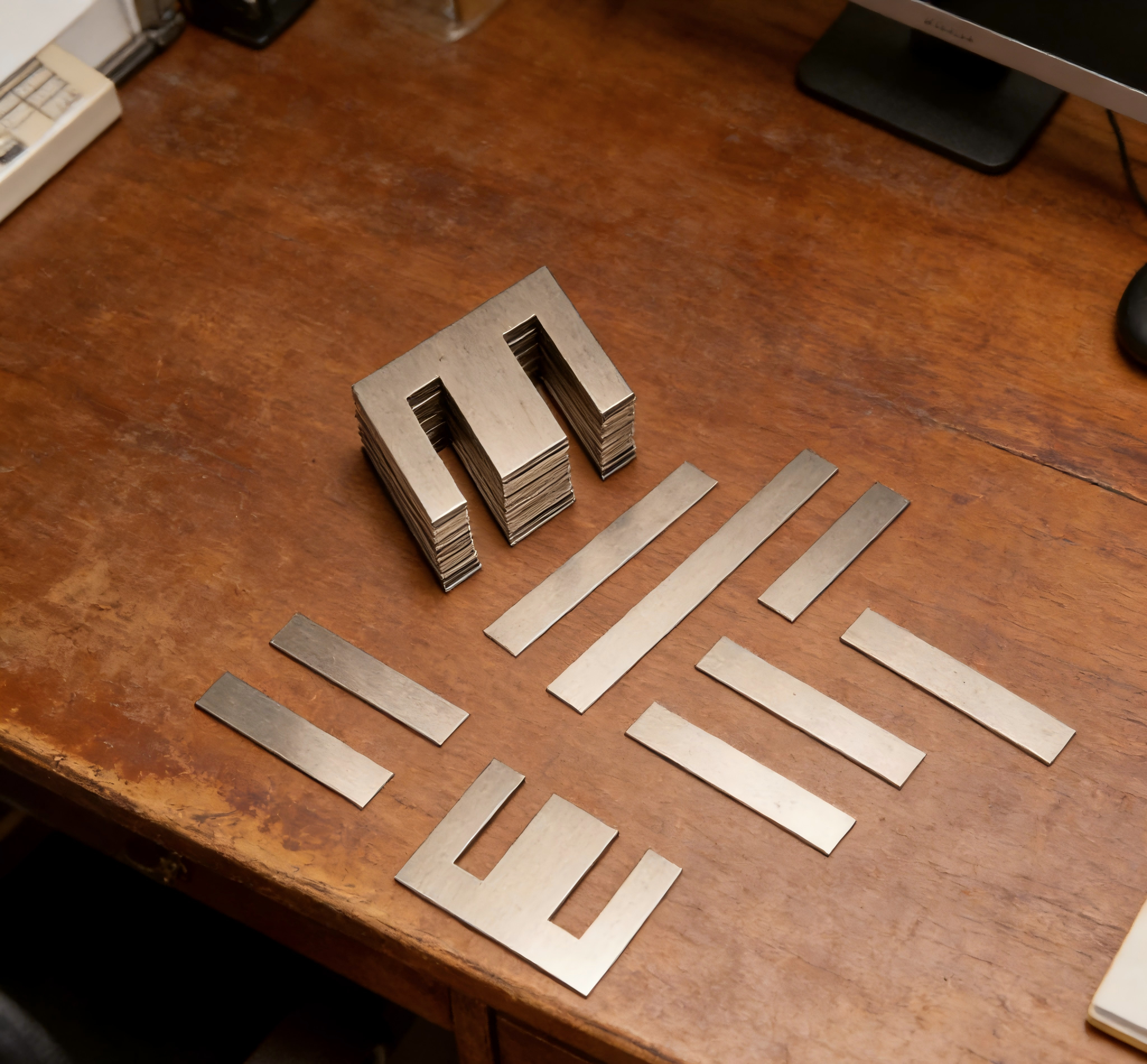
Where the core is laminated rather than wound, thickness becomes a first-order parameter rather than a footnote. Distribution transformer cores are produced as CRGO silicon steel lamination cores, amorphous cores, dry type transformer cores, oil immersed transformer cores and distribution transformer laminations, with strip thickness options of 0.2 mm, 0.23 mm, 0.27 mm and 0.3 mm. The same family serves both dry-type and oil-immersed transformer builds.
Laminated formats include stepped laminated cores, lap joint cores, right-angle laminated cores, EI/ED/SD/CD cores, stepped cores and thin strip cores. Specific designs in the same range include the Unicore (a type of folded core), the Step-Lap Core, and distribution gap cores made from amorphous material or FeSi.
Permalloy cores: grades 1J85, 1J79 and 1J50
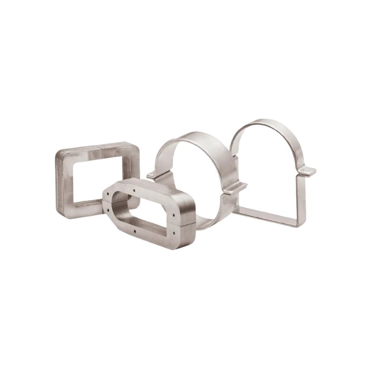
Permalloy is a Ni-Fe permalloy alloy (80Ni-4Mo-Fe), classified as a high-permeability magnetic alloy and precision magnetic material. Unlike CRGO, it is specified by grade rather than thickness: 1J85, 1J79 and 1J50. Core types in this family include toroidal permalloy cores, precision current transformer cores, high-permeability sensor cores, Ni-Fe alloy lamination cores and custom permalloy cores. Typical duty spans energy management, energy monitoring, electricity, medical X-ray and special power supply.
Thin strip cores: 0.05–0.15 mm
Thin strip cores move in the opposite direction from lamination stock: thinner material, lower eddy losses, different handling. Gauges are 0.05 mm, 0.08 mm, 0.1 mm and 0.15 mm, in model ranges MU, GT050, GT080 and GT100, and in materials that include both silicon steel and permalloy. The format family covers amorphous thin strip cores, nanocrystalline thin strip cores, silicon steel thin strip lamination, toroidal high-efficiency cores and low-loss transformer cores, supplied as Block Core, Pulse Transformer Core and Toroid Core.
Sizing Parameters: Dimensions, Rated Power and Loss Scaling
Sizing converts material choice into a physical part, and it reduces to three numbers: loss ceiling, dimensional envelope, and rated power.
- Loss ceiling. ≤1.0 W/kg at 1.5T, 50Hz for standard NCW no-cut cores; ≤1.2 W/kg at 1.5T, 50Hz for custom toroidal cores.
- Dimensional envelope. NCW cores: 50–200 mm core diameter. Custom toroidal cores: OD 30–300 mm, ID 15–200 mm, H 10–150 mm.
- Rated power scaling. NCW cores scale from 100 VA (NCW100) to 5,000 VA (NCW2500). Custom toroidal cores extend the same CRGO family from 50 VA to 10 kVA.
- Thermal boundaries. -40°C to 120°C for NCW cores; -40°C to 130°C for custom toroidal cores. Other products in the same catalogue, such as instrument and voltage transformers, are designed for -40°C to +155°C environments with indoor and outdoor installation on 50Hz and 60Hz power systems.
A workable order of operations at the discovery stage: fix the loss ceiling first, because it eliminates material grades that cannot meet it; then fix the dimensional envelope, because it eliminates formats; then confirm rated power against the model table.
Core Format Reference
Format is the third decision layer after material and gauge. The table below maps the formats named in this guide to the material and geometry they belong to.
| Format | Material family | What defines it |
|---|---|---|
| Toroidal wound core (no-cut) | CRGO silicon steel | Continuously wound strip forming a closed path; NCW range, 50–200 mm core diameter, 100–5000 VA, ≤1.0 W/kg at 1.5T, 50Hz |
| Custom toroidal wound core | CRGO silicon steel | Non-standard geometry; OD 30–300 mm, ID 15–200 mm, H 10–150 mm, 50 VA–10 kVA, ≤1.2 W/kg at 1.5T, 50Hz |
| Step-lap core | CRGO silicon steel lamination | Named laminated design in the distribution transformer core range |
| Unicore (folded core) | CRGO silicon steel lamination | Named folded-core design for distribution transformer cores |
| Distribution gap core | Amorphous material or FeSi | Gapped distribution core offered in two material builds |
| CD / CD cut core | CRGO silicon steel lamination | C-type and cut C-core geometry within the EI/ED/SD/CD family |
| EI lamination core | CRGO silicon steel lamination | Stacked lamination format in the EI/ED/SD/CD family |
| Block core | Silicon steel, permalloy | Thin strip format; 0.05–0.15 mm gauge, MU / GT050 / GT080 / GT100 |
| Toroidal permalloy core | Ni-Fe permalloy (80Ni-4Mo-Fe) | Precision and sensor duty; grades 1J85, 1J79, 1J50 |
| Nanocrystalline / gap / CD core | Silicon steel, nanocrystalline | Low current transformer and sensor cores; 0.66 kV / 0.72 kV; classes 0.2, 0.5, 1, 0.5S, 0.2S |
Step-by-Step: Specifying a Core From Duty to Drawing
- State the electrical duty. Distribution transformer, instrument transformer, current sensor, choke/reactor, or special power supply. Duty points to the material family: CRGO silicon steel for the power-frequency path, permalloy (1J85 / 1J79 / 1J50) or nanocrystalline where precision dominates, thin strip for pulse and higher-frequency duty.
- Set the loss ceiling. ≤1.0 W/kg at 1.5T, 50Hz for standard NCW cores; ≤1.2 W/kg at 1.5T, 50Hz for custom toroidal cores. Write it into the specification as an acceptance number, not as a description.
- Pick the gauge. 0.2 / 0.23 / 0.27 / 0.3 mm for CRGO distribution transformer laminations; 0.05 / 0.08 / 0.1 / 0.15 mm for thin strip cores.
- Choose the format. No-cut toroidal where a closed magnetic path is preferred; step-lap, lap joint or unicore for laminated distribution cores; CD, CD cut core or EI lamination for stacked assemblies; block or toroid for thin strip.
- Fix the dimensional envelope and rated power. Confirm OD, ID and H against the model table (NCW100 to NCW2500; custom toroidal OD 30–300 mm, ID 15–200 mm, H 10–150 mm) and confirm VA within 100–5000 VA or 50 VA–10 kVA respectively.
- Validate before committing to volume. Request a sample or quotation against the finished drawing and confirm the three measurable parameters — core loss, dimensions, grade — before the production window opens.
Use Cases: Matching Parameters to Real Applications
Distribution transformers
Distribution cores use CRGO silicon steel laminations at 0.2–0.3 mm, in dry-type and oil-immersed builds, in step-lap, lap joint, unicore and distribution gap formats. Where no-load loss is the dominant design target, amorphous cores reduce no-load losses by 70% to 80% compared with traditional CRGO cores (Electrical Trader). CRGO nevertheless remains the volume material, holding 79.6% of the transformer core market by material type in 2024 (Mordor Intelligence) — a split worth understanding before assuming an alternative material replaces the default option.
Current sensors and low-current instrument transformers

Sensor-class duty is where permalloy and nanocrystalline cores replace CRGO. Low current transformer and low current sensor cores are made of silicon steel and nanocrystalline, in toroidal, gap core, CD core and nanocrystalline formats, rated at 0.66 kV and 0.72 kV with accuracy classes of 0.2, 0.5, 1, 0.5S and 0.2S. Applications sit in energy management, energy monitoring, electricity, EV charging and industrial control. Where the requirement is precision current measurement rather than power throughput, permalloy grades 1J85, 1J79 and 1J50 become the reference specification.
Instrument transformers (current, voltage, combined)
Instrument transformers use silicon steel cores with epoxy resin, copper winding and aluminium alloy housings. Voltage transformers are rated at 10 kV, 35 kV and 110 kV with capacities of 10 VA, 15 VA, 30 VA, 50 VA and 100 VA and accuracy classes of 0.2, 0.5, 1 and 3. Current transformers cover primary currents from 5 A to 5000 A with 1 A or 5 A secondary output and accuracy classes from 0.2S to 10P. Combined current and voltage transformers run at 10 kV / 35 kV, 5 A to 3000 A, accuracy class 0.2 and insulation level 42 kV.
High-frequency chokes, filters and reactors
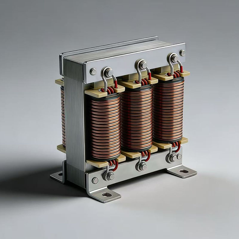
Chokes and reactors translate core parameters into circuit behaviour. Chokes are offered with an inductance range of 1 µH to 100 mH, rated current from 1 A to 1000 A and rated voltage of 0.4 kV, 6 kV or 10 kV, with insulation class options of B, F and H. Dry-type series reactors run from 0.1 mH to 1000 mH at 50 A to 5000 A and 0.4 kV, 6 kV, 10 kV or 35 kV, using silicon steel cores with natural or forced air cooling. This is the application where thin strip cores in 0.05–0.15 mm gauges and block or toroid formats are most often specified.
Medical X-ray and special power supply
Permalloy and thin strip cores are used in medical X-ray and special power supply equipment, where precision magnetic material and low-loss formats matter more than raw volt-ampere capacity. Both families appear in the same catalogue alongside the CRGO ranges, which means a project can source power-frequency and precision cores from a single specification conversation.
Comparison Table: Material and Parameter Reference
| Parameter | NCW no-cut CRGO core | Custom toroidal CRGO core | Thin strip core | Permalloy core |
|---|---|---|---|---|
| Material | CRGO silicon steel | CRGO silicon steel | Silicon steel, permalloy | Ni-Fe permalloy alloy (80Ni-4Mo-Fe) |
| Grade / model designation | NCW100, NCW150, NCW200, NCW300, NCW350, NCW500, NCW750, NCW1000, NCW1500, NCW2000, NCW2500 | Non-standard (custom) core | MU, GT050, GT080, GT100 | 1J85, 1J79, 1J50 |
| Strip thickness | CRGO lamination band 0.2 / 0.23 / 0.27 / 0.3 mm | Same CRGO lamination band | 0.05 / 0.08 / 0.1 / 0.15 mm | — |
| Core loss | ≤1.0 W/kg at 1.5T, 50Hz | ≤1.2 W/kg at 1.5T, 50Hz | Low-loss construction (no W/kg figure published in catalogue) | — |
| Dimensional envelope | Core diameter 50–200 mm | OD 30–300 mm, ID 15–200 mm, H 10–150 mm | Block, pulse transformer and toroid formats | Custom and standard toroidal formats |
| Rated power | 100–5000 VA | 50 VA–10 kVA | — | — |
| Operating temperature | -40°C to 120°C | -40°C to 130°C | — | — |
| Application industries | Power supply; transformer core projects | Power transformer, current/voltage transformer, inductor/choke, power electronics, renewable energy, EV charging, industrial control | Energy management, energy monitoring, electricity, medical X-ray, special power supply | Energy management, energy monitoring, electricity, medical X-ray, special power supply |
FAQ
Which standards and grade designations should a transformer core specification reference?
Power transformers and reactors are governed by the IEC 60076 series standards, which specify general requirements and testing for cores (International Electrotechnical Commission). Material designations are handled separately by family: permalloy cores are specified by grade 1J85, 1J79 or 1J50, while CRGO silicon steel lamination cores for distribution transformers are specified by strip thickness — 0.2 mm, 0.23 mm, 0.27 mm or 0.3 mm. Application-side requirements in this segment commonly include customized design, low loss and high efficiency, high insulation strength, RoHS and CE compliance, long service life and anti-corrosion performance. A complete specification therefore pairs the IEC 60076 reference with a material grade or thickness, a core loss ceiling, and a dimensional envelope.
What dimensional and power range is available for custom CRGO toroidal cores?
Custom toroidal wound cores are made from CRGO silicon steel and are built to a customizable range of OD 30–300 mm, ID 15–200 mm and H 10–150 mm, with a rated power range of 50 VA to 10 kVA, core loss of ≤1.2 W/kg at 1.5T, 50Hz and an operating temperature range of -40°C to 130°C. Standard NCW no-cut toroidal cores cover 50–200 mm core diameter at 100–5000 VA with core loss ≤1.0 W/kg at 1.5T, 50Hz and -40°C to 120°C operation, across model designations NCW100 through NCW2500. Thin strip formats such as Block Core, Pulse Transformer Core and Toroid Core are available in 0.05 mm, 0.08 mm, 0.1 mm and 0.15 mm gauges.
Is CRGO silicon steel or permalloy the more economical choice?
They serve different duties rather than competing on one price point. CRGO silicon steel lamination cores carry the volume demand — grain-oriented laminated steel held a 79.6% share of the transformer core market by material type in 2024 (Mordor Intelligence) — because they cover distribution transformers, chokes and general power conversion. Permalloy cores use a Ni-Fe permalloy alloy (80Ni-4Mo-Fe) in grades 1J85, 1J79 and 1J50 and are specified where permeability and precision drive the design, such as precision current transformer cores, high-permeability sensor cores and medical X-ray equipment. The practical rule: specify CRGO where the loss ceiling and rated power define the job, and permalloy where measurement accuracy defines it, then compare quotations against the same drawing and loss limit.
Can samples be validated before a production order?
Sampling is the practical way to confirm a core before committing to volume, because the parameters that decide acceptance are measurable: core loss (≤1.0 W/kg for NCW cores and ≤1.2 W/kg for custom toroidal cores at 1.5T, 50Hz), dimensional envelope (for example OD 30–300 mm, ID 15–200 mm and H 10–150 mm on custom toroidal cores), and material grade (1J85, 1J79 or 1J50 for permalloy; CRGO silicon steel for lamination and toroidal cores). YadooTEK, the brand of Wuxi Yado Electromechanical Co., Ltd. in Jiangyin City, Wuxi, Jiangsu Province, supplies magnetic materials and transformer cores and can be contacted for sample or quotation requests at lucien@yadootek.com, by telephone on +86 13912495853, or through its WhatsApp line.
What lead time should be planned for a custom core order?
Core projects operate in a mode involving 30 working days, which is the planning figure to use for custom and non-standard cores. That window covers design and manufacturing for CRGO silicon steel cores, permalloy cores and thin strip cores before shipment. Because material grade, strip thickness, loss ceiling and dimensional envelope all have to be fixed before that window opens, buyers running a distribution transformer, current sensor or choke programme should freeze those four parameters at the specification stage rather than during the build.
Conclusion: Four Parameters, One Drawing
Core selection stops being ambiguous once it is reduced to material family, strip thickness, loss ceiling and dimensional envelope. CRGO silicon steel remains the reference material for power-frequency duty, at 79.6% of the market by material type in 2024 (Mordor Intelligence). Permalloy grades 1J85, 1J79 and 1J50 cover precision and sensor duty where permeability outranks power handling. Thin strip cores in 0.05–0.15 mm gauges serve pulse, choke and special power supply applications. Sizing then follows the model table — 50–200 mm core diameter and 100–5000 VA for NCW cores, or OD 30–300 mm and 50 VA–10 kVA for custom toroidal cores.
What separates a usable specification from a vague one is that each number is written down and traceable to a duty. Loss ceiling, dimensions and grade should be verifiable on the sample, not inferred after delivery.
Next step: catalogue, sample or quotation
YadooTEK (Wuxi Yado Electromechanical Co., Ltd.) manufactures CRGO silicon steel cores, permalloy cores, thin strip cores and laminations for distribution transformers, current sensors, instrument transformers and chokes, from a 1,000 m² facility in Jiangyin City, Wuxi, Jiangsu Province, China.
Download the product catalogue: YadooTEK Transformer Core Catalogue (PDF)
Sample or quotation requests: lucien@yadootek.com · Tel +86 13912495853 · WhatsApp
Website: www.yadootek.com

Have Questions or Need More Details?
Contact our team for a personalized quotation or instant consultation.
Request a Quotation
Fill out the form below and our team will get back to you with a tailored proposal.
WhatsApp Direct Chat
Prefer to chat in real-time? Message us on WhatsApp for instant assistance & quick answers.
- Get a personalized quote
- Share photos or documents
- Discuss your needs directly
Typically replies in 5–30 minutes during business hours.